This tree, excluding the big mp4 files, can be cloned on your
system; then you could "git pull" for updates:
git clone git://hsw2021.gnudd.com/hsw2021-www.git
The "main" course tree, that includes both a "hw" subdirectory and a "sw" one, can be cloned like this:
git clone git://hsw2021.gnudd.com/hsw2021.git
Both repositories grow during the course.
Exercises live in a separate file clled exercises.html.
Everything is in this single file (I hate fragmented pages). But here is a table of contents (one entry per lesson) as a shortcut.
Lessons may be "remote" or "mixed mode".
For remote lessons, I try to put out slides and/or videos, for the first part of the lesson, while the latter half is done in videoconferencing (edu-meet or Big Blue Button). So material here is around an hour worth (usually a little less) for every lesson. It is definitely more compressed than an interactive lesson: watching a lesson is so boring that I tried to save you the time. And that's why there is less than two hours for a 2-hour lesson.
As an alternative, sometimes I might prefer a two-hours interactive lesson, and in this case the related material will be published later (usually later in the same day), and will be the same content just more compressed (i.e., I repeat the same stuff while recording). The whole interactive lesson may be recorded or not. If so, I won't link it here, but share the link with enrolled students.
For "mixed mode" lessons, I don't yet know. Most likely we'll record in the classroom, which means it is much worse for those who can't attend.
The videos are 15-20m each. Specific length is listed here below for each of them. They are on Youtube, feel free to share the link, because I (almost) don't swear when I record myself. As an alternative, you can download the mp4 file. If you watch online please ensure to make the image big enough. For the mp4 version (which is the original I uploaded, so it is either the same or better quality) I verified that what I write is readable. Please remember that most of what I show is committed as well.
This is an introduction to the course, showing some hardware devices.
We are using git all the time (and you need it elsewhere too). Some of you are already acquainted with the tool, but some are not. This is a description of why and how it is done its way, while showing some commands in real repositories.
If you are new to git, please do not be scared, getting proficient takes time and experience. Please try to get the basic ideas out. If you are already used to it, I hope you can get something new from this lesson.
Some questions and study hints are here.
Advanced Git Use is an article I published in 2010 but it's still current. I translated it from Italian in a hurry, and later tried to fix the disgusting English. I also removed a section I don't find relevant any more.
The man pages gittutorial(7) and gittutorial-2 are a
good starting point if you look for a tutorial. The man
page git(1) and all pages for the sub-commands
(e.g. git-log(1)) are very good reference material. Please
note that sub-comamnds are separated by a space, but man pages use the
dash (because the argument of man must be a single word).
If you miss local man pages, ore prefer a web render of the very same information, you can use the following ones; but please remember that the locale man refers to exactly the version you have installed, while the web describes the "current" one, whatever it means -- not a problem for git, which has a stable interface, but a real issue sometimes.
This time we talk about PCB design. But this is not a tutorial about practical use of a specific tool, but more a collection of ideas and suggestions.
You are expected to install Kicad (which is Free Software) and get acquainted with it. You may want to design something for the project work you'll deliver at the end of the course. If you prefer a different tool, that you can legally use, that's not a problem, but please consider whether you'll be legally allowed to use it again in the future.
There are three video and one slide set. And please be reassured that I'm not asking kicad at the exam.
And tdc.pdf is the schematic of the board we 'll use later on.
Some questions and study hints are here.
Finally, Italian-speaking (or, better, Italian-listening) readers may enjoy a presentation of TDC-1.0 I made at the End Summer Camp 2019. It is a shorter version of a 2-hour conference session where I had my oscilloscope and everything to actually show the board in action.
Version 1.1 of TDC (that I designed in March 2021) includes more peripherals, but it is derived from the one shown here. In git history you see the previous version as well.
You all know C language, so let's see at how the build process works behind the hood. We start with hello and go to hell, a stripped version without the O (perating system). Then, we start looking at a reverse polish notation calculator, that will allow, in the next lesson, to get acquainted with the linker.
Please remember to read the commit messages, where everything is explained.
I suggest reading my compact summary of the language features; it might be a trivial refresh, or difficult stuff. Either way, you are expected to get fluent with that material. If you need a book, I suggest the K&R, most of the rest is very bad: authors tend to waste vast amount of pages in solving problem that you'd never do in C language in the real world: C is for operating systems internals and microcontrollers, that's it.
For A-C-X and A-C-X-more there is an Italian version on Linux.it. Thie Italian version is the original, and then I translated to English, so Italian is a little more fluent and it features fewer typos.
Some questions and study hints are here.
uint32_t a suitable type in many situations?Here we complete the povacca example by showing how we can use a custom ELF section in the object file to create an array from independent sources.
I don't repeat the steps in the repository, because the commit messages explain them all. This time I show things in a different way.
The second video shows how to cross-compile hell for ARM, so we see the basic use of a cross-compiler, and then find that the ARM executable can actually run on the PC, and why (hint: it's binfmt_misc on Linux).
Some questions and study hints are here.
$(wildcard) in the Makefile?The slide-set of today shows an overview of the simple development system (gcc, make, editor) that we use (which actually is still used as the basement for most "modern" IDEs), as well as the cross-compilng environment.
The commits (up to the lesson-05 tag) show how to
build a standalong freestanding "hello.c" file for the Versatile
board, which can be easily emulated by Qemu. Please remember that
everything is explained in the commit messages, so "git log
--reverse" is your friend.
The lesson was recorded for the students, but not linked here. No short video is there so far, because everything is explained in the commit messages (did I already say so?).
About inline assembly (that you are not expected to master at this point), you may be interested about a 30m talk I made at the last Linux day (in Italian), linked below.
Finally, please take a look, if you want, at the first version of the test program I wrote for the TDC board, (next commit after the tag) and think about it.
Some questions and study hints are here; question 5.2 is about the above program.
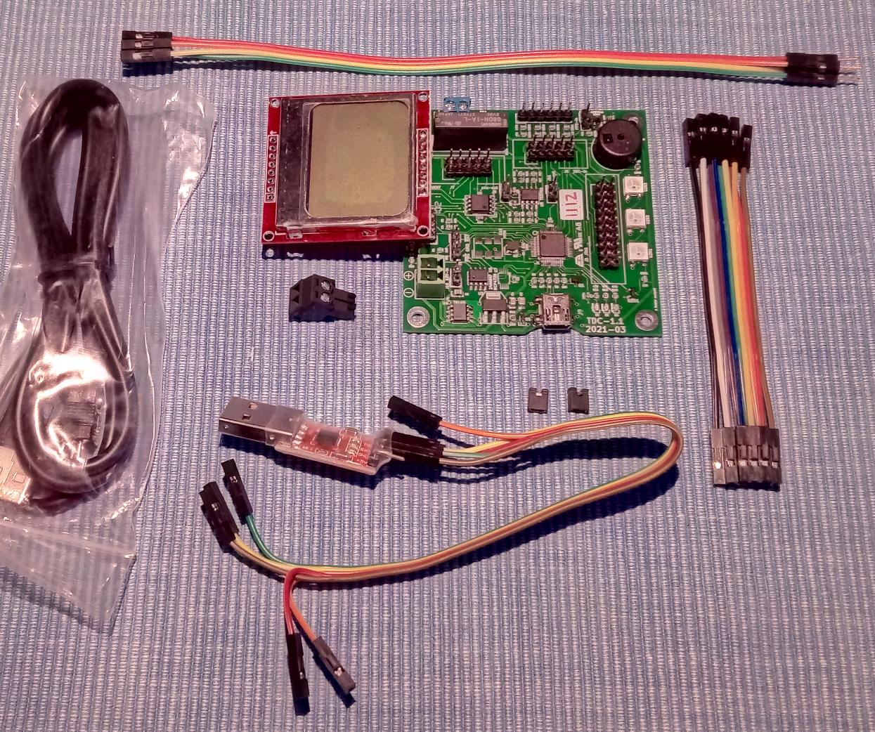
CROSS_COMPILE in the Makefile?vello?This is the TDC kit that we use during this course. It was delivered to each student:
It includes:
The green connector (J10) says "12V", but anything from 7V upwards works. Actually, until we use 5V-powered devices (the relay and the neopixels) you can even feed 5V and everything will work.
If it was a product, we should sell it rated for 7V-12V, but we know we can use a wider supply range in our own lab (or room). Even a voltage higher than 12V is ok, up to 24V or more, but then be careful about heath dissipation in the 7805 device.
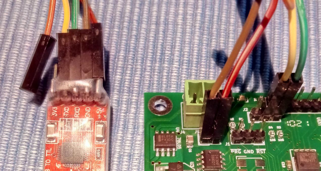
Please note that if you power the board with the USB cable, it will enter USB-programming (as opposed to serial programming). In the first iterations we will use serial programming. If you can't feed the green connector with 5-12V, it's possible to power it through the serial adapter, using the 2-pin strip that lives near the green connector. Pin 1 (double-border) is GND (pin 1 is always GND in my designs -- guess why). Moreover, the positive and negative pins are in the same order as those in the green connector (which are written on the PCB).
Please be careful about polarity. the positive goes to +, and negative (GND) to -. Otherwise you'll emit smoke (I didn't try, but I won't be surprised).
The UART pin-strip is GND-TX-RX, in this order. In the figure above we don't need to route GND to pin 1 of the UART connector, obviously. If you don't know why, let's discuss.
To force programming mode, you must power-on (or reset using the specific pin) while keeping the "PRG" pin shorted to ground.
You can either use the provided jumper, to keep "PRG" low at power on, or you use your tweezers: short "PRG" to "GND" while ticking "RST", as shown in the figure (it's not exactly the same board, but that's irrelevant).
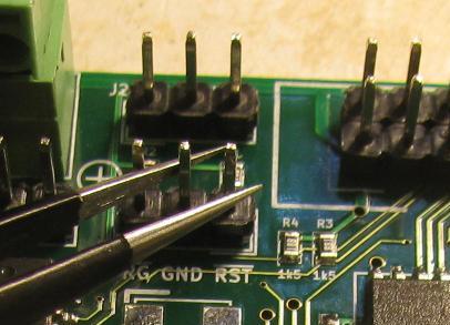
As you see, the "PRG GND RST" pin strip breaks the rule that GND is always pin 1, exactly to make this operation easier, but pin names are written on the PCB.
The board, as shipped, is pre-programmed with the test procedure. The binary is committed, but the source is not (yet).
If you want a quick video tutorial about power and resetting, I recorded one, available as tdc-power.mp4 (30MB, 7:48).
Finally, the page lpc-programming explains how to flash a .bin file to the LPC processor (i.e. the TDC board).
In this lesson we were still using the Versatile board as emulated by Qemu, and we introduced how to manage time, i.e. the "jiffies" variable, and access to registers.
If you really want a set of videos about this, please refer to the ones of last year (http://hsw2020.gnudd.com). The (much slower) video of this year's lesson was made available to attending students, and later I recorded a short video that summarizes the concepts.
Please remember, though, that the commit messages explain
everything (much better than the video, in my opinion). So please
get used to "git log --reverse -p commit.." to actually
look at the set of code changes with the associated explanation.
Moreover, in this lesson, I planned to complete the discussion about the cross-compiler, and standardized on using gcc-8.2 from now on. I suggest we all use the same version, which you can rebuild using my simple script (it's not the best script, it's just the simplest possible). You can clone and run the script with the following command:
   git clone git://hsw2021.gnudd.com/arm-toolchain.git
   cd arm-toolchain
   ./tools/build-generic configs/gcc-8.2.0
CROSS_COMPILE
accordingly.
Clearly there are many possible builds of the compiler, including the ones provided by the distributions, but it sometimes happens that different optimization techniques (in different versions) generate different code and we wouldn't understand each other. Also, sometimes a too-new compiler can break some code by using new and unexpected optimization techniques. To avoid dealing with such incompatibilities, we should really all use the same version; experienced people can well deal with differences and fix problems, but the class is not experienced, yet.
Some questions and study hints are here.
/DISCARD/ in the linker script?In this lesson we introduce the ARM processor, and its Thumb variant, in order to be able to read its assembly language and thus be able to debug low-level code.
Then, we are running code on real hardware (the TDC board). We load the program to RAM, as this simplifies hardware configuration, and finally introduce a GPIO API, whose design choices are good but not optimal.
There are slides for ARM and GPIO. For everything else, see the commits and the commit messages.
Some questions and study hints are here.
THRE to be empty?This time we moved to flash programming. The current code base can't be loaded with program because we now use a linker script to laoded into processor flash. How to do that is explained in the commit message, please get used to that (in windows you can just copy the binary to external storage, and then reset to make it run).
This introduces the concept of a data section, which has a different
run address ("VMA" in objdump -h) and load address ("LMA").
We rely on /DISCARD/ to ensure that every bit is build-tested,
avoidind #ifdef that drops the code altogether.
Finally, we introduce a "bad" implementation for udelay().
Some questions and study hints are here.
.rep and .endrIn this lesson we used the GPIO API to actually drive the output leds, and implemented a (bad) neopixel driver. The code discussed and written during the lesson is in the associated commit messages.
Some questions and study hints are here.
#error in C language?regs[] to access registers?ARRAY_SIZE?Today we introduced Kconfig in the project, and used it for a pair
of "configurable" items (flash/ram running and the value of HZ).
Then we introduced time_before() and time_after().
As usual, the commit messages contain most of the information. In the code please ignore the boring details (especially I don't care about the 22k lines of the Kconfig machinery, with its own Makefile intricacies).
Some questions and study hints are here.
obj-y in the Makefile?.config and what is defconfig?HZ and CONFIG_HZ?Important note: The compiler we built in lesson 6 has some issues, even if I successfully used it in other projects. The libgcc it creates is not correct for Cortex-M0, because it uses instructions for later families of processors. As a result, as soon as your code does a division (which is not implemented in hardware and requires a function call) it will hang, likely with an "illegal instruction" trap -- which is not handled yet).
So, we'll now change compiler, because printf performs divisions (and thus it exposed the bug to me). The simplest approach is running arm-none-eaby as provided by your distribution (be it Ubuntu or whatever you choose, including the simulated environment under other operating systems). As an alternative, you can get the official "Linaro" compiler, which is currently hosted under developer.arm.com.
I placed a copy in hsw2021.gnudd.com so you can get it with a single click. This is re-archived with a different directory name, which is simpler. I offer three different compression formats:
For completeness,
The simplest option is uncompressing under /opt and
then pointing CROSS_COMPILE to it:
export CROSS_COMPILE=/opt/gcc-arm-linaro-8.3/bin/arm-none-eabi-
The above environment variable is what I'll use for the course from now on.
What is described here is on show in the set of commits of this lessons. As usual, commits are as short and to the point as to be understandable. And don't forget that I don't care about register names or values, I only care about the underlying ideas and concepts.
This time we introduced the Phase Locked Loop that is part of the microcontroller. This logic block is able to output a different internal CPU clock from the external oscillator frequency.
Most processors nowadays include such a block, of varying complexity. In the most simple case, the clock generator is simply a divider: the processor can run at a fraction of the external oscillator. For example the AVR family of microcontrollers feature such a divider. You may want to run slower to save power, because the current needed by a logic circuit is mostly proportional to the clock speed.
The PLL in this microcontroller is able to multiply the oscillator frequency. The internals are not trivial, and we are not interested in them. The code I committed deals with the proper registers but you should happily ignore them (and I do either: I forgot it all after writing the code, and that's how it should be).
So, what we end up with is a Kconfig option that allows to choose a
frequency multiplier (between 1 and 4, because of how hardware
capabilities of the processor), and the CPU_FREQ constant
in the code depends on that value. As a result, we can configure for
12MHz or 48MHz, or intermediate values, and everything works.
To verify that it works you might check that the timing
of leds.bin is the same with the various configurations,
but usleep() features a different number of NOP
instructions.
There are two interesting details in the PLL code: use of weak functions and use of a build-time constant calculation.
The oscillator block of this microcontroller can be fed with either the internal RC oscillator (which runs at 12MHz) or the external quartz or clock circuit (from 1MHz to 25MHz). The internal oscillator is not sharp enough to support USB communication (which requires a sharp 48MHz clock) so most boards actually use the external oscillator. The TDC we use here has a 12MHz oscillator.
The PLL driver must support both situations, but as said it's most common to use the external oscillator. The way we enact a sensible default while allowing board-specific code to override it is with a weak function: the main PLL code calls board_get_clksel(), which can be defined elsewhere, but it meanwhile provides a weak implementation, that selects the oscillator (as opposed to the internal RC frequency). At link time, if a strong (i.e. normal) symbol exists, the linker will pick it; if none is there the weak function will be used instead.
The other thing to be careful with, when raising internal clock
frequencies, is that some peripheral may not keep up with the new speed,
and just fail. Here, the flash controller is specified up to 20MHz,
and if the CPU clock is faster we must introduce wait states (see
FLASHTIM register, page 44 of the user manual).
Now, we might provide another Kconfig option for the wait states
(and I actually did, in other projects), but the best approach is
calculating the wait states automatically. When we know the CPU
frequency (it's the CPU_FREQ constant) and the
requirement for wait states (wait states = (frequency - 1) / 20MHz,
with integer division), we can place the calculation in the code.
The compiler will perform the expression for us at build time, and
the output assembly code will just use the constant value, with no
overhead.
The second set of commits in this lesson introduces printf. I pick my own pp_printf implementation, which is small and complete -- moreover you can choose your own tradeoff between size and features. This is something I wrote for the White Rabbit project (precision timing for physics research), where the original code base was using a strange, not standard-compliant, source file, of unknown copyright status.
Besides printf itself, that you may want to look at, here we
introduce two important ideas: use of attribute((format))
so the compiler can spit warnings about format specifiers, and use
of PROVIDE in the linker script.
Usually the compilers warns about printf formats (e.g., you
use "%i" for unsigned long, instead
of "%li"-ffreestanding) and do not rely on system
header files. Se we need to tell the compiler that our functions use
printf-style format specifiers. This is done
in pp-printf.h for the pp_printf() set of
functions, but we want the same to happen for printf(), because
this is what applications will use.
Then, we need to actually allow applications to
call printf() and sprintf() instead
of pp_printf() and pp_sprintf(). Most text books will
suggest to ``#define printf pp_printf'', but this is bad
for several reasons: not least because your object files won't show
the same names you expect to see.
To fit this need we use PROVIDE, a feature of the
linker script: we can tell the linker to provide pp_printf as a
suitable alternative to printf if no such symbol is available
during the final link.
You might object that we could instead define a weak symbol in some
way, because the problem being faced is similar. You are invited to
do so, but you'll likely find that there is no simple way to achieve
the target without some run-time overhead. You might also object that
we may use PROVIDE instead of weak in the PLL
case above; but then please note that printf is a core
system function whereas oscillator selection is PLL-specific. A number
of drivers will benefit from weak default over time, and we don't
each driver to force a change in a global file, like the liner script is,
for modularity and ease of maintenance of the code base.
PROVIDE means in the linker script?Here we saw how to use the "garbage collect sections" feature of the linker to discard everything we do not use. In the example, the neopixel program is not using printf, so we want to save space in the binary (i.e., in processor flash) by discarding printf -- and anything else that we build but do not use in the specific application.
Then, we talk a little about power consumption in modern logic. This is somehow a simplicistic description of the subject matter, but it is a good approximation of reality. This is used, BTW, to solve exercise 11.2, while looking at the official docs to get some confirmation.
The next topic is the stack: stack overflows are a serious mishap and you may waste days to find why your code is misbehaving. Worse, an overflow may get unnoticed and make serious damages in production. Here I show how to detect stack overflows and be able to forget about the problem: if it happens, when you add a feature too much, the system hangs, plain and simple.
Finally, processes. The last video shows how task execution is normally scheduled in simple firmware implementations (those with a simple "while(1)" loop) and in classic real-time operating systems. The description is begging the question: how would you do it better?
--gc-sections linker option?KEEP in the linker script?This time we dealt with the implementation of udelay. As usuall, all the documentation is in the commit messages and the code.
In the commit you find two examples more, that were not discussed yet in the classroom. You are expected to take a look and possibly run the code. Or -- even better -- write your own.
Some questions and study hints are here.
This lesson discusses about real-time scheduling, introduces the most important schedulers (RM and EDF) and offers an implementation of the "task" idea that relies on a single stack (but we still have no preeemption).
With this, we eventually managed to cover all of the topics of my "two hours operating system" talk, so here is a link to the thos material, which should be a quick recap of everything we have seen so far. The recorded video is 90 minutes, it was taken at a conference.
Some questions and study hints are here.
__task_first and __task_last in the linker script?struct task?This lesson merged a number of sub-branches, visible in git history.
First of all, we introduce sscanf, command parsing and a shell example program. This allows, so late, to add your own code features and test them interactively.
Then we fix the neopixel example. This makes a few different steps
to make the library function independent of the processor architecture
and the board. Now any PCB (with any architecture) can use this library
file, if it provides <board.h> and possibly
(according to what board.h uses) __gpio_set
and __gpio_get. Last but not least, the sub-microsecond
waiting code, based on NOP instructions, is made independent
of the clock speed.
Finally, we implement a sharp timestamping procedure. Both as inline function and as standalone function. The latter is useful to disassemble what came out of the original code. This is implemented in C first and in assembly later. With this, we have the first real TDC polling application.
Some questions and study hints are here.
__gpio_get and __gpio_set are now inline functions?errno.h used for?This lesson is a recap about basic Unix concepts and shell programming. It is not exam material.
The topics here are shown because they are considered useful, and may help understanding the way I do things -- even if the target of activities is the microcontroller board.
In a perfect world it should all known stuff, because students of the master course are expected to already be acquainted with basic OS concepts. If they are known, I might show a different point of view; if they are not, I hope they are interesting. If any wants to dig further, feel free to ask and I'll give you proper pointers -- better than a random network search.
This lesson brings no exam questions, as promised.
Here I covered the various steps that you need to perform in order design and produce a PCB. This, again, is not exam material.
This lesson brings no exam questions, as promised.
In this lesson I described the most important communication busses: I2C, SPI and UART (including the RS-485 variant). The last part of the material, as well as showing the SPI driver code, was delayed to the next lesson.
Here I completed the discussion of the previous slides.
What I find especially important in the RS485 hardware implementation is that you should not connect together the tx-enable and rx-enable pins in the transceiver.
All RS485 transceivers look the same, and rx-enable is active low. So most users just connect together tx-enable and rx-enable, because you either receive or transmit. But this is wrong (unless you are very short of gpio pins) because you need to turn off the transmitter after your data left the device. Instead if using a timer or minitoring some status bit, the easiest way to know when TX is over is be reading back your own tx data: when you read back it all, you turn off the transmitter. You are never early and you are never late. Moreover, the transceiver enters low-power-mode when both tx and rx are disabled. If connect them together, this will never happen.
We also looked at my spi "driver", and the choice of splitting
configuration from run-time status in the device structure. The
configuration can be const and live in read-only memory.
In microcontrollers you have way more flash than RAM, so this is
usually a good choice. Clearly, the run-time structure needs a
pointer to the configuration, and some clock cycles to access it; so
this split only make sense if the configuration itself is
significantly bigger than the size of a pointer.
Then, we discussed the need for assert and panic, as well as the requirement to make such event visible to the user, both on the serial port and as a visual message using the diagnostic leds.
The implementation for panic I use relies on a weak function to select "no-diag-leds" as a default fall-back, so each application and provide its own pair of leds (and their polariry), or just not offer the feature -- for example, if you have no diagnostic leds.
struct spi_cfg and struct spi_dev separate items?struct spi_ibuf and struct spi_obuf are different
despite being identical?__attribute__((format(printf)))?__attribute__((noreturn))?In this lesson we introduced interrupts. As usual, most of the documentation is in the commit messages (and the CPU manual and so on). The final part of the slide-set, about threaded interrupts, is still to be covered.
No new material this time, discussion proceeded with the previous subject matter. Then, (actually, at the beginning) a WCET measuring tool was added, with a Kconfig selection of its activity or lack thereof.
Final lesson about interrupts, where the code (and implementation concepts) about threaded interrupt management is introduced.
Some questions and study hints are here.
irq_request/irq_free useful?In this lesson Sara Zanzottera described the Zanzocam project, build by a group where she was the only software developer.
Her slides are here: Presentazione.pdf.
container_of doing?list.h.Exam rules changed in 2022. The previous rules does not apply any more.
You will be asked 10 questions, and you must reply correctly to 8 of them in 90 minutes. The questions are chosen from the ones written above at the end of each lesson.
The exam is done with pen and paper, in the classroom. This is why students are given 10 minutes per answer, plus 10 minutes overhead.
You can use the laptop, to look at commits and whatever, but without any network connection.
In the questions, you are expected to describe with your own words one technical point. Answers must be as tidy and to the point as possible (i.e., no hand-waving). You choose your questions, you must know the answer.
Exercises are no more.
The project work is no more.
Still, if you want you can deliver one, showing you approach to the solution of one of the problems I asked, or whatever. If you want to do it, you also know what is expected.